

 By iCarsoft Official Store Technical Team, Automotive Diagnostics Editors · Updated September 1, 2026 · OEM technical references checked
Quick Answer
The P0625 code means the controller detected a low electrical-state result in the generator field/F terminal circuit. It does not prove battery voltage is always low, the alternator must be replaced, or F identifies one universal pin. Save the complete scan and operating conditions, identify the exact architecture, and test accessible mechanical and electrical paths before selecting a repair.
What Does the P0625 Code Mean?
P0625 is standardized as Generator Field/F Terminal Circuit Low. The description names a monitored result, not a guaranteed failed part. The reporting controller, suffix, current/pending/permanent status and related faults decide which test branch is relevant.
The regulator may be inside the generator or managed through the powertrain controller, with dedicated field, monitor or network paths. F-terminal meaning and direction vary. Separate the low circuit classification from battery state of charge and measured charging output.
Record battery voltage, generator command, load and available field data while following the OEM charging-system test and using a stable power source when required. A displayed value comes from the controller and may be substituted, filtered or unavailable. Confirm units and signal source before comparing it with a physical measurement.
Ford PE13-003 appendix data lists P0625 on several specified applications under generator-related comprehensive-component monitoring. It confirms the terminology but does not supply a universal voltage threshold or replacement decision.
Separate P0625 from adjacent fault families
| Code | General description | Key distinction |
|---|---|---|
| P0625 | Generator field/F terminal circuit low | Low state in the defined field circuit. |
| P0622 | Generator field/F terminal circuit | Base circuit monitor without the same low classification. |
| P0626 | Generator field/F terminal circuit high | The corresponding high-state branch. |
| P0562 | System voltage low | A system-level voltage result, not the same F-terminal code. |
Record the complete P0625 description. Manufacturer suffixes, the module that stored it and companion faults can materially change the diagnostic path.
P0625 Symptoms and Likely Causes
P0625 symptoms depend on whether the fault is active and on the vehicle’s fallback strategy. Record what the driver and modules actually reported. A symptom list is not a parts list, and the absence of a symptom does not make the stored evidence irrelevant.
The battery or generator lamp may illuminate, but lamp logic varies.
Lights, steering assistance or modules may behave abnormally as system voltage changes.
A battery can be a consequence, contributor or separate fault; test it rather than assuming.
Harness movement, temperature or high electrical demand can expose a field-circuit problem.
Practical cause-checking order
- Accessible connection: loose battery, generator or controller connections and damaged F-terminal wiring.
- Circuit or shared path: poor engine/body grounds, fuse or fusible-link trouble, or belt/drive problems.
- Supporting system: a battery condition that distorts charging tests and must be corrected first.
- Named component: generator regulator or field hardware that fails the manufacturer test.
- Controller or software: controller driver, communication or calibration trouble only after external charging paths pass.
Did P0625 appear after recent work? Recheck every disturbed connector, ground, bracket, fluid, adjustment, part number and setup step related to the charging-system field control or feedback path. Record battery disconnection, jump starting and software history. A post-repair code does not prove that the newly installed component is defective.
How Serious Is P0625, and Can You Drive?
Arrange diagnosis promptly. When the warning is steady, operation remains normal and the owner’s manual permits it, a short light-load trip to a repair facility may be reasonable. Avoid demanding use until the charging-system field control or feedback path is understood. P0625 does not provide a universally safe distance.
Tell the repairer exactly when the symptom occurred, including temperature, load, speed, start state and recent service. Do not deliberately reproduce a severe symptom on public roads merely to collect data. Stop sooner when another warning or a safety-related change appears.
Stop and arrange a tow if the engine stalls, steering or braking assistance changes, lights dim severely, the battery swells or vents, wiring smokes, a burning odor appears, or a red charging warning is paired with unsafe operation
Batteries can vent explosive gas and high-current charging circuits can arc. Remove jewelry, use eye protection, follow disconnect order, and keep test leads clear of the belt and fan. Never short a field terminal to power or ground.
How to Diagnose P0625 in the Right Order
-
Save the complete fault record
Scan all accessible modules before clearing anything. Save P0625 wording, suffix, reporting module, status, freeze frame and companion codes. Record supply voltage and the relevant available data for the charging-system field control or feedback path. Note the failure order, recent repairs and whether a restart changes the behavior. Keep the original report for later comparison.
-
Identify the VIN-specific monitor and architecture
Use the VIN, engine, transmission and equipment codes to obtain the current wiring diagram, connector views, monitor description and bulletins.
The regulator may be inside the generator or managed through the powertrain controller, with dedicated field, monitor or network paths. F-terminal meaning and direction vary. Separate the low circuit classification from battery state of charge and measured charging output. Confirm software identifiers and service-action eligibility directly; a bulletin for one application does not establish coverage for another.
-
Inspect the accessible physical path
Follow the safety procedure, then inspect the connectors, locks, seals, terminals, clips and harness routing for the charging-system field control or feedback path. Look for heat, abrasion, fluid entry, corrosion, tension and unsuitable prior repairs. Check the supporting mechanical or fluid path named in the service information. Photograph evidence before correcting it.
-
Prove circuits and physical conditions
Use a calibrated multimeter, current clamp, oscilloscope or charging-system analyzer, and approved battery support equipment as the procedure requires. Prove feeds and grounds under the specified load, then test signal or control integrity at the correct states. Isolate components before resistance tests. Never bridge a controller pin to battery or ground, and do not substitute a continuity beep for a load or waveform test.
-
Compare supported command and response
Record battery voltage, generator command, load and available field data while following the OEM charging-system test and using a stable power source when required. Compare scan evidence with the external measurement and companion faults. A command does not prove physical movement, pressure, current or torque. A missing PID or active test is a coverage limitation, not evidence that the vehicle component failed. Stop any test if operation becomes unsafe.
-
Choose the supported repair and setup
Repair the path that failed its test, then correct the reason for damage and restore routing or adjustment. Confirm part application, required fluid or fasteners, programming authority and any relearn before replacement. Treat a controller as a late branch after its powers, grounds, inputs, outputs and current service information have passed.
Specifications are vehicle-specific. There is no universal voltage, resistance, current, pressure, waveform, timing, temperature, percentage or drive cycle for P0625. Test state, connector location and system design change what a valid value means. Use only specifications for the exact VIN and do not transfer the OEM example in this article to another application.
P0625 Repairs and Typical Costs
The correct P0625 repair follows the failed test. A terminal repair, restored supply, corrected fluid/mechanical condition, proven component replacement, software action or controller work are different outcomes. Replace neither the named part nor a large assembly from the generic code alone.
After installation, recheck connector seating, harness clearance and every setup step. If an OEM bulletin appears relevant, document the vehicle eligibility, installed calibration and prescribed action. The existence of the bulletin in the references does not promise warranty, free repair or a software cure for other vehicles.
| Possible path | Current US estimate |
|---|---|
| Initial diagnosis and evidence capture | VIN-specific quote |
| Confirmed connector, wiring, supply or ground repair | VIN-specific quote |
| Proven sensor, switch, actuator or mechanical repair | VIN-specific quote |
| Applicable software, setup or controller work | VIN-specific quote |
There is no single national P0625 repair price because these rows are alternative outcomes. Ask for an itemized estimate showing diagnostic time, parts, labor, fluids, programming access and verification. Location, taxes, related damage and warranty eligibility change the total. Do not add the rows together or authorize an assembly without the supporting failed test.
Using iCarsoft CR Ultra P for P0625
On a supported vehicle, iCarsoft CR Ultra P can retrieve accessible module faults, save available freeze frame, display ECU-provided live data and create a diagnostic report. For P0625, preserve the original evidence and compare related modules before clearing an erasable record.
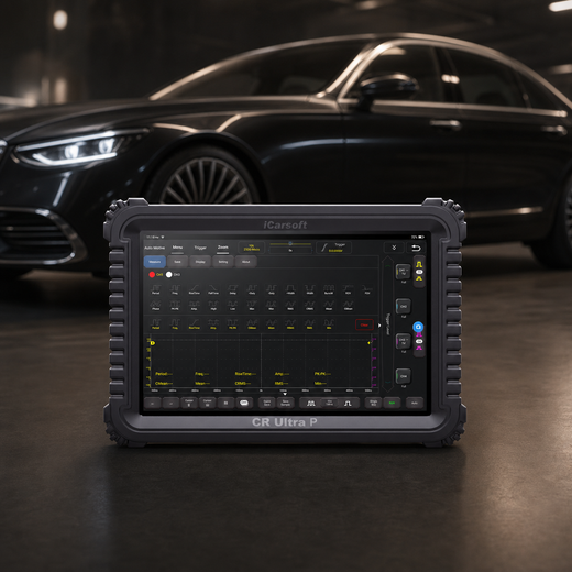
Preserve the charging-system field control or feedback path evidence
iCarsoft CR Ultra P
Review supported codes and relevant live data together. Confirm the exact VIN, controller access, PIDs and any requested active test with iCarsoft before purchase; generic product capabilities do not guarantee a P0625-specific function.
Check current CR Ultra P price and availabilityCheck CR Ultra P compatibility by VINThe official product page describes full-system diagnosis and bidirectional functions, but the exact charging-system field control or feedback path data or output test depends on vehicle, ECU and software. Follow OEM prerequisites and stop for abnormal operation. A coding or J2534 feature does not itself supply the manufacturer file, subscription, authorization or procedure for an OEM bulletin.
Know the measurement boundary. The scanner reports information supplied by the vehicle. It does not directly prove terminal tension, circuit load capacity or the physical condition of the charging-system field control or feedback path. It also cannot replace a calibrated multimeter, current clamp, oscilloscope or charging-system analyzer, and approved battery support equipment when the OEM procedure requires them. Interpret commanded and reported values alongside measured evidence.
Verify the P0625 Repair
After repair, verify connector locks, terminal seating, harness clearance, fluid or mechanical setup, and stable controller supply. Save post-repair findings, then clear only erasable records through the approved procedure after retaining the original evidence. Battery disconnection is not a substitute for correcting P0625.
Run the manufacturer’s applicable verification conditions in a safe workshop or route. Compare the original operating state with current data for the charging-system field control or feedback path, and check current and pending faults in related modules. One clean start or idle period does not prove that every conditional monitor has completed.
If P0625 returns, compare its suffix, status, failure order and operating conditions with the saved baseline before replacing another part. Revisit the failed branch and inspect anything disturbed. Keep mechanical repair, monitor completion, readiness and local inspection eligibility as separate outcomes.
A permanent P0625 can remain immediately after a successful repair. If the vehicle stores it as a permanent DTC, a scan tool or battery disconnect cannot erase it. Once current and pending faults are absent, the OBD system removes the permanent record only after the applicable monitor reruns and passes.
Related Generator Field/F Terminal Code Guides
P0625 Frequently Asked Questions
Does P0625 mean the charging-system field control or feedback path component is bad?
No. P0625 describes a low electrical-state result in the generator field/F terminal circuit, not a confirmed part. Test accessible wiring, supplies, grounds and supporting mechanical conditions, then follow the exact monitor tree. Replace a component only when its branch fails or an applicable OEM action specifically supports it.
What should I check first for P0625?
Save every module’s codes and freeze frame before clearing. Confirm the full definition, suffix and VIN architecture. Then inspect recent work, connectors and shared supplies. Those low-cost facts determine whether the next test needs a calibrated multimeter, current clamp, oscilloscope or charging-system analyzer, and approved battery support equipment or a manufacturer-specific functional procedure.
Can I drive with the P0625 code?
Only consider a short light-load trip when operation is normal and the owner’s manual permits it. Stop if the engine stalls, steering or braking assistance changes, lights dim severely, the battery swells or vents, wiring smokes, a burning odor appears, or a red charging warning is paired with unsafe operation. The code number cannot establish a safe mileage allowance, and another warning can make the situation more urgent.
Why did P0625 return after a part was replaced?
The original circuit or supporting-system fault may remain, the part or setup may be wrong, or the first diagnosis may have confused a monitored result with a failed component. Compare the new failure conditions with the saved record and recheck every disturbed connection before buying another part.
How much does a P0625 repair cost?
A VIN-specific estimate is required because diagnosis may lead to wiring, a supporting mechanical repair, a verified component, software or a controller. Ask which failed test supports the quote and whether diagnosis, taxes, setup and post-repair verification are included.
Can CR Ultra P diagnose and clear P0625?
On a supported vehicle, CR Ultra P can organize available faults, freeze frame, live data and reports, and can clear erasable records after repair. Confirm exact ECU coverage. It cannot force-clear a permanent DTC or replace physical circuit and charging-system field control or feedback path measurements.
The iCarsoft Official Store Technical Team maintains the store's fault-code library. This guide organizes published manufacturer evidence and verified product information; it does not document a hands-on test of a particular vehicle or claim an individual engineer's review.
Technical and cost references
- Snap-on Diagnostic Trouble Codes (DTC) List. Current generic terminology cross-check for P0625; OEM suffix and service information take priority.
- Ford PE13-003 Appendix I subject-vehicle DTC data. Lists P0625 as Generator Field/F Terminal Circuit Low on specified Ford applications; it is not a universal diagnostic threshold.
- California Bureau of Automotive Repair — On-Board Diagnostic Test Reference. Permanent DTCs are removed by the vehicle after applicable verification, not by a scan-tool erase command.
Product information: Official iCarsoft CR Ultra P page.
Editorial note: This educational guide supports diagnostic planning and does not replace the current service manual, safety instructions, or professional diagnosis for your VIN. Source information was checked September 1, 2026. Apply only the procedures and specifications for the exact vehicle; product functions depend on vehicle, ECU, software, and access requirements.


