

 By iCarsoft Official Store Technical Team, Automotive Diagnostics Editors · Updated August 31, 2026 · OEM technical references checked
Quick Answer
The P0502 code means the monitored vehicle-speed sensor A circuit or input has been classified as low. It does not mean the car is merely traveling slowly or that one particular wheel sensor has failed. Save all module faults, identify the actual speed-signal source, and compare sensor, transmission, ABS, and engine data before testing the relevant electrical path.
What Does the P0502 Code Mean?
P0502 concerns the vehicle-speed input monitored by the controller. Its low classification describes an unacceptable signal condition relative to the monitor's expectations, not a command to drive faster. The complete definition and manufacturer suffix must be checked because speed information can travel through different components on different vehicles.
A vehicle may obtain speed information from a transmission or driveline sensor, or from another module that processes wheel-speed data. The ECM's displayed vehicle speed is therefore not always a direct measurement from one nearby sensor. Trace the actual source and communication route before deciding which connector or component to test.
Sensor A is an OEM identifier rather than a universal front-left, rear-right, or transmission-side location. A wiring diagram and component location view establish what it means for the exact VIN. Also distinguish vehicle speed from engine speed, transmission input speed, and output-shaft speed; they are related but not identical parameters.
GM bulletin PI1489, dated June 2015, describes water intrusion into the manual-transmission output-speed sensor on specified Cadillac ATS and Chevrolet Corvette applications with P0502. By contrast, a Volkswagen Golf/GTI specification-book entry refers to a brake-control-unit error message. These narrow examples show why the same base code cannot justify one universal sensor replacement.
Vehicle speed low, erratic, and transmission-speed faults
| Code | General description | Key distinction |
|---|---|---|
| P0500 | Vehicle speed sensor A | A general vehicle-speed fault requiring source identification. |
| P0502 | Vehicle speed sensor A circuit low | The low-input branch, not proof of low road speed. |
| P0503 | Vehicle speed sensor A intermittent/erratic/high | A different monitored behavior; capture dropouts or implausible changes. |
| P0720 | Output speed sensor circuit | A transmission output-speed circuit that may be related but is not interchangeable on every VIN. |
Compare signals at the source and receiver. Correct speed in one module with missing speed in another can point toward the information path. Missing speed everywhere can suggest a shared source or power concern. Confirm the architecture before drawing either conclusion.
P0502 Symptoms and Likely Causes
A P0502 code may affect only a warning light, or it may accompany speedometer, shifting, cruise-control, or stability-system concerns. The effects depend on which modules rely on the missing information. Document the exact symptoms rather than assuming that every vehicle will enter the same fallback mode.
The displayed road speed may be wrong or absent, but a normal speedometer does not prove every controller receives valid data.
Harsh, delayed, or restricted shifts may occur when a transmission depends on an affected speed input.
Cruise or stability-related functions may be limited depending on the vehicle and companion faults.
Moisture, vibration, heat, or damaged wiring may produce a problem that is absent during a stationary scan.
Practical cause-checking order
- Connector and harness faults: inspect terminal fit, water entry, corrosion, routing near rotating or hot parts, and damage after driveline or wheel-area service.
- Supply, ground, or signal path: determine sensor technology first, then test the required circuit under the manufacturer's specified conditions.
- Sensor mounting or target condition: check installation, clearance, contamination, and the relevant tone ring or reluctor only where the architecture uses one.
- Upstream module or network problem: investigate ABS, transmission, power-supply, and communication faults when they affect the source of vehicle-speed data.
- Incorrect configuration or internal failure: review replacement part suitability, relevant setup, and controller tests after the external evidence is complete.
After transmission, hub, or wiring work: confirm the correct connector, sensor installation, harness clips, and component application. If wheel or tire specifications changed, document that too and check the OEM requirements. Do not assume that recalibration can compensate for an electrical dropout or damaged reluctor.
How Serious Is P0502, and Can You Drive?
Obtain diagnosis promptly because speed information can affect several systems. A short trip may be reasonable only if the owner's manual permits it, speed can be judged safely, shifting is predictable, and no braking or stability concern exists. Do not use cruise control or test a questionable vehicle in demanding traffic.
A warning that disappears after restarting does not establish that the signal is reliable. Avoid high-speed road testing to provoke a dropout. If normal driving cannot be carried out safely, use recovery instead. P0502 does not provide a universally safe speed, distance, gear, or remaining operating time.
Stop and arrange a tow for unpredictable gear engagement, loss of drive, serious slipping, repeated stalling, unsafe power loss, abnormal braking behavior, overheating, fluid leakage, or an urgent brake or stability warning. Follow the owner's manual. Arrange professional transport if the vehicle cannot be controlled or operated predictably.
Rotating wheels and driveline components are dangerous during speed testing. Do not run a vehicle in gear on a household jack or improvise a wheel-spin test. Use the manufacturer's supported test procedure and proper equipment. Keep probes and clothing clear of moving parts, and have a helper operate the scanner during any permitted road test.
How to Diagnose P0502 in the Right Order
-
Save speed-related faults from every accessible module
Record P0502 status, suffix, freeze frame, and engine, transmission, ABS, and communication codes before clearing. Save available vehicle speed, individual wheel speeds, input/output speeds, voltage, and selected gear. Note whether the speedometer failed and whether the symptom followed water exposure, a repair, or a particular road condition.
-
Identify the speed source and receiving controllers
Use the VIN-specific system diagram to trace sensor A and the route by which vehicle-speed information reaches the reporting controller. Identify sensor technology, module processing, network messages, and any shared supplies. Confirm the actual transmission and braking-system configuration rather than choosing a sensor from a generic code description.
-
Inspect wiring, mounting, and the relevant target
With the vehicle safely secured, inspect plugs, seals, terminal retention, harness routing, sensor mounting, and any accessible tone ring or reluctor identified by the service manual. Look for corrosion, debris, damage, or disturbed clips. Do not alter sensor clearance, hammer a target ring, or remove drivetrain parts without the correct procedure.
-
Prove supply, ground, and signal integrity
Follow the correct test method for the installed sensor, using an appropriate meter or oscilloscope. Check signal presence at the source and receiver where directed, and perform required load or voltage-drop tests. Passive and powered sensors do not share identical checks. Never apply external power to an unidentified signal terminal.
-
Compare module speed data during a safe valid test
When supported, compare the originating speed value with the ECM, transmission, ABS, and dashboard information under the prescribed conditions. Look for dropouts or disagreement rather than expecting identical units for every PID. Correlate the event with voltage and companion faults. A stationary zero-speed value is normally expected and does not diagnose P0502.
-
Confirm the repair and required configuration
Repair the demonstrated connector, harness, sensor, target, supply, or data-path fault. Verify replacement application and any setup after module or drivetrain work. Investigate internal controller failure only after inputs and external paths pass. Recheck the original failure condition and complete the monitor-based verification before describing the repair as successful.
Specifications are vehicle-specific. Sensor output type, pulse count, voltage, resistance, target spacing, and module processing differ by vehicle. Do not use one universal speed-sensor resistance or frequency rule. Confirm units and conditions, and remember that a steady meter reading can miss a brief dropout that requires a properly configured oscilloscope.
P0502 Repairs and Typical Costs
The correct P0502 fix restores valid speed information along the actual source-to-controller path. That may require a terminal repair, harness correction, proven sensor replacement, target repair, or resolution of an upstream module fault. Replacing a wheel-speed sensor at random can leave a transmission-originating or network-related problem unchanged.
If water intrusion or physical damage is confirmed, correct the cause as well as the failed component. Check seals, clips, cable clearance, and replacement suitability. Use any OEM bulletin only when the exact vehicle and prerequisites match; the GM example is not evidence that every P0502 comes from a wet output-speed sensor.
| Possible path | Current US estimate |
|---|---|
| Full-module diagnosis and speed-signal testing | VIN-specific quote |
| Connector, harness, supply, or ground repair | VIN-specific quote |
| Proven sensor, reluctor, or related mounting repair | VIN-specific quote |
| Confirmed module configuration or separately diagnosed drivetrain work | VIN-specific quote |
A generic wheel-speed sensor quote cannot represent every P0502 repair. The failed component may be elsewhere, and access, sensor integration, labor, taxes, and setup vary. Ask for a written estimate naming the actual signal source and the failed test. The table lists alternative repair paths rather than costs that always apply together.
Using iCarsoft CR Eagle P for P0502
On a supported vehicle, iCarsoft CR Eagle P can scan accessible modules, preserve available freeze frame, display live data, and save diagnostic reports. For P0502, comparing the relevant engine, transmission, and ABS information can help locate where valid speed evidence disappears.
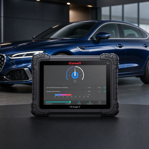
Trace speed information across the vehicle
iCarsoft CR Eagle P
Review supported vehicle, wheel, input and output-speed data with their correct units. Confirm the exact VIN, transmission, ABS module access, and required PIDs before purchase.
Check current CR Eagle P price and availabilityCheck CR Eagle P compatibility by VINThe official page lists full-system and bidirectional capabilities, but available data and tests vary by ECU. There may be no appropriate stationary active test for this concern. Do not improvise wheel or driveline movement to use a menu item; follow the vehicle manufacturer's safe road-test or workshop procedure.
Know the measurement boundary. The tablet cannot directly prove a sensor waveform, terminal voltage drop, reluctor damage, bearing condition, or wiring under load. Use the specified meter, scope, mechanical inspection, and supported lifting equipment. Live data is the module's interpretation of a signal, not an independent measurement of every point in the circuit.
Verify the P0502 Repair
After repair, confirm sensor mounting, connector locks, seals, and clearance from moving components. Save the completed repair measurements and post-repair scan. Clear erasable DTCs only after preserving the initial evidence, using the OEM procedure rather than disconnecting the battery to remove the warning.
Repeat the safe conditions that originally produced the problem and allow the applicable monitor to run. Check current and pending codes, speedometer behavior, predictable shifting, and agreement among the relevant supported speed values. One stationary scan cannot prove that a fault triggered during movement is repaired.
If P0502 returns, compare the new data path, fault order, and operating state with the original record. A dropout in one module but not another deserves different investigation from a missing source signal. Verify readiness and any related system warnings separately; a clear display is only one part of successful validation.
A permanent P0502 can remain immediately after a successful repair. If the vehicle stores it as a permanent DTC, a scan tool or battery disconnect cannot erase it. Once current and pending faults are absent, the OBD system removes the permanent record only after the applicable monitor reruns and passes.
Related Vehicle and Transmission Speed Code Guides
P0502 Frequently Asked Questions
Does P0502 mean I was driving too slowly?
No. It describes a low vehicle-speed input relative to the monitor's expectations. A stationary zero reading can be normal. Diagnose the signal source, circuit, and operating conditions instead of attempting to clear the fault by driving faster.
Where is vehicle speed sensor A?
Its location depends on the VIN and drivetrain. Speed may come from a dedicated sensor, a transmission or driveline source, or another module's processed information. Sensor A is not a universal wheel position; trace it using the actual wiring and system diagrams.
Can the P0502 code appear with a working speedometer?
Yes. Different modules may obtain or process speed information through different paths. A correct dashboard display does not prove that the reporting controller receives valid input. Compare the relevant source and receiver data and investigate companion faults.
Can I drive with P0502?
Only if the owner's manual allows it and speed indication, shifting, braking, and vehicle control remain safe. Stop for unpredictable engagement, loss of drive, serious slipping, or urgent warnings. A road test should not expose you or others to an unsafe vehicle.
Why did replacing a speed sensor not fix P0502?
The selected sensor may be the wrong source, or wiring, terminals, target condition, supplies, module data, or setup may still be faulty. Confirm the failed test and exact application rather than replacing another sensor by trial and error.
Can CR Eagle P locate a P0502 signal problem?
Supported live data and module scans can help compare speed information along its path. Confirm the required VIN and ECU coverage. Physical waveform quality, voltage drop, target condition, and wiring load capacity still require external tests.
The iCarsoft Official Store Technical Team maintains the store's fault-code library. This guide organizes published manufacturer evidence and verified product information; it does not document a hands-on test of a particular vehicle or claim an individual engineer's review.
Technical and cost references
- GM PI1489 — MIL Illuminated, P0502 Vehicle Speed Sensor Circuit Low Voltage Specified manual-transmission ATS/Corvette water-intrusion example; not universal sensor replacement guidance.
- Volkswagen Golf and GTI Quick Reference Specification Book — P0502 DTC chart Brake-control-unit message example illustrates architecture differences; no numerical thresholds transferred.
- Snap-on Diagnostic Trouble Codes (DTC) List Generic vehicle-speed and transmission-speed code distinctions.
- California BAR — On-Board Diagnostic Test Reference Permanent-record and monitor-verification principles.
Product information: Official iCarsoft CR Eagle P page.
Editorial note: This educational guide supports diagnostic planning and does not replace the current service manual, safety instructions, or professional diagnosis for your VIN. Source information was checked August 31, 2026. Apply only the procedures and specifications for the exact vehicle; product functions depend on vehicle, ECU, software, and access requirements.


