

 By iCarsoft Official Store Technical Team, Automotive Diagnostics Editors · Updated September 27, 2026 · Technical sources checked
Quick Answer
The C0032 code identifies the left front wheel speed sensor supply in the cited reference. Confirm the full OEM description before testing. It does not prove that the battery, sensor or ABS module failed. Use the correct wiring diagram to establish the supply path and prescribed test conditions, then measure the fault before choosing a repair.
What Does the C0032 Code Mean?
NHTSA Appendix K lists C0032 as Left Front Wheel Speed Sensor Supply with a subfault. Apply that reference label only when the complete VIN-specific OEM wording agrees. The full fault record determines the test branch.
A sensor-supply fault concerns the electrical conditions needed by the installed sensing arrangement. It is different from a tone-wheel label or a generic vehicle-speed code. The word supply does not reveal a universal voltage, pin number or wire color. Those details depend on the exact brake-controller and sensor architecture and must come from the vehicle’s current service information.
A measurement is useful only when its reference point and test state are known. Write down where the probes were connected, whether the sensor remained connected and which ignition or module state the procedure required. Comparing an unloaded reading with a loaded specification can produce an incorrect conclusion even if the number was recorded accurately. Follow the prescribed comparison rather than inventing a threshold.
NHTSA Appendix K separates C0032, Left Front Wheel Speed Sensor Supply, from C0031, Left Front Wheel Speed Sensor, and C0030, Left Front Tone Wheel. This separation supports distinct diagnostic questions; it is not a vehicle-specific test chart. No universal voltage, resistance limit or controller-replacement instruction is established by this code-reference table.
If C0032 appeared after a sensor replacement, record the old and new part numbers and what happened when the connector was disturbed. A new component does not prove that the supply path is healthy, and a temporary improvement does not identify the original failure. Compare the complete returning code with the original record before disconnecting more parts.
Preserve the module wording and suffix before clearing.
Separate C0032 from adjacent fault families
| Code | General description | Key distinction |
|---|---|---|
| C0032 | Left Front Wheel Speed Sensor Supply | Supply branch; obtain the exact electrical test conditions. |
| C0031 | Left Front Wheel Speed Sensor | Sensor/circuit/signal record is not identical to supply. |
| C0030 | Left Front Tone Wheel | Rotating-reference diagnosis requires physical evidence. |
| C0035 | Right Front Wheel Speed Sensor Supply | Different wheel channel in the reference mapping. |
Record the complete C0032 description. Use the exact module, suffix and OEM procedure to select the test path.
C0032 Symptoms and Likely Causes
Record C0032 symptoms and fault status; symptoms alone cannot identify a failed part.
Check whether companion faults share a proven cause.
A current or stored supply-related fault may accompany a warning. Preserve the exact suffix and the conditions of detection instead of assigning a universal warning-lamp pattern.
If the supported channel is absent or unreliable, record it alongside the supply fault. Missing live data alone cannot distinguish an unsupported PID from a physical electrical failure.
A fault that appears after steering or suspension movement may justify careful routing inspection. Do not move an unsecured vehicle or reach near moving components to provoke it.
Companion supply or communication faults deserve review against the wiring architecture. They do not establish a common failed battery, fuse or controller without the relevant measurements.
Practical cause-checking order
- Confirm supply wording: Confirm C0032 and its complete OEM definition; do not apply a sensor-supply procedure to an alternative legacy chassis-code meaning.
- Trace the correct branch: Use the exact wiring diagram to identify the left-front channel and any genuinely shared supply or return. Avoid guessing from wire colors or neighboring connectors.
- Check connector integrity: Inspect retention, corrosion, seal condition and cable damage before electrical isolation. Record disturbed connections and any repair history.
- Measure in the required state: Test the supply path with the sensor and controller in the state required by the diagnostic chart. A disconnected reading may not represent the operating circuit.
- Verify upstream evidence: Check the controller’s relevant feed and return only as the chart directs. A missing sensor-side supply is evidence to trace, not automatic proof of an internal ABS module defect.
Did C0032 appear after recent left-front sensor, harness, hub or battery work? Recheck the documented connections, parts and setup steps affected by that work. Record battery and software history; a post-repair code does not prove the new part is defective.
How Serious Is C0032, and Can You Drive?
Arrange prompt brake diagnosis and follow the owner manual. Do not assume ABS or stability assistance remains available. Abnormal pedal effort, pulling, fluid loss, dragging or a red brake warning requires stopping safely and arranging recovery. The code cannot establish a safe driving distance.
Record brake warnings, pedal changes, fluid loss and recent service. Do not induce wheel slip or emergency braking to test assistance on public roads; warning-state assessment comes before any functional verification.
Stop and arrange a tow if braking changes, pedal effort or travel is abnormal, a wheel drags, fluid leaks or a red brake warning appears.
Follow the exact shutdown and pressure-release procedure before accessing brake components. Support a raised vehicle securely, keep clear of moving parts and never energize unidentified circuits. Do not perform public-road emergency-stop experiments.
How to Diagnose C0032 in the Right Order
-
Preserve the supply fault and companion records
Save C0032 with its full suffix, reporting module and current or history status. Capture available event information and note recent battery, sensor or harness work. Record related faults before clearing. If braking, wheel security or pedal behavior is abnormal, secure the vehicle and arrange qualified assessment before attempting a movement-based confirmation or comparing live wheel-speed values.
-
Identify the circuit and its allowed test state
Obtain the VIN-specific wiring and diagnostic procedure. Identify the actual sensor architecture, supply and return path, connector views and permitted test equipment. Read the required ignition state and connection conditions before probing. Do not substitute a familiar voltage from another model or assume that every two-wire sensor can be tested by the same resistance measurement.
-
Inspect the left-front connections and route
With safe access and the prescribed shutdown procedure, inspect the left-front connector and cable route. Look for damaged insulation, poor retention, moisture evidence, strain or a trapped lead after recent work. Photograph an abnormal connection before disturbing it. If the diagram shows an intermediate connector, include it in the inspection rather than testing only the ends of the visible lead.
-
Measure the supply path with the prescribed reference
Carry out the specified supply measurements using the required reference point, connection state and approved adapters. Record the conditions with each result. When a reading fails, determine which section has actually been assessed before moving upstream. Do not use jumper power, an oversized test lamp or unapproved back-probing that could damage a controller output or a sealed terminal.
-
Isolate the demonstrated loss without guessing
Follow the service chart’s isolation sequence to distinguish the sensor load, harness, connection and controller-side supply path. Disconnect components only when and how the procedure permits, since doing so may change circuit behavior or create additional records. Verify any proposed controller diagnosis against its relevant power and return checks; a code or one sensor-side reading alone is insufficient.
-
Confirm restored supply and usable speed information
Repair the documented defect and restore connector seals, retention and routing. Complete required setup, then repeat the relevant supply and functional checks under the approved conditions. Confirm that the left-front speed information is usable where supported and the original fault does not recur during the specified verification. Preserve the post-repair evidence and identify any untested intermittent condition.
Specifications are vehicle-specific. Use the exact VIN specifications, approved test points and required operating state. No generic value or drive cycle can replace the applicable procedure. Manufacturer examples here do not establish specifications for other applications.
C0032 Repairs and Cost Planning
A C0032 repair must address the demonstrated failure. Do not replace an assembly from the code alone.
Recheck installation and required setup after repair. More than one sensor-related code can suggest a shared electrical issue, but it does not prove that all wheel channels use a common supply. Trace the actual diagram before grouping faults together. Conversely, one affected corner does not automatically clear the controller of suspicion. The diagnostic record should show where the supply condition changes and which section was actually tested.
Ask the shop to name the failed branch and the measurement supporting each proposed repair.
Authorize diagnosis before parts while the cause remains uncertain.
| Possible path | Quote basis |
|---|---|
| Repair the connector or harness after a documented circuit failure | VIN-specific quote |
| Correct the demonstrated physical or installation fault | VIN-specific quote |
| Replace only the component that fails its prescribed test | VIN-specific quote |
| Complete required setup and safe functional verification | VIN-specific quote |
Request an itemized, VIN-specific quote for the proven repair, setup and verification. Check applicable warranty coverage.
Using iCarsoft CR Pro S for C0032
On a supported vehicle, iCarsoft CR Pro S can save accessible faults, available freeze frame, live data and diagnostic reports. Preserve the C0032 evidence before clearing.
Compare available brake-controller records before and after repair. The report supports diagnosis but cannot replace the OEM physical and functional checks.
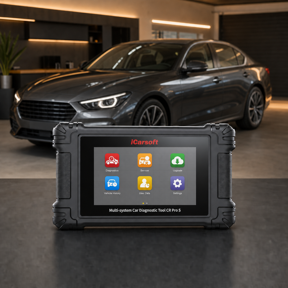
Preserve the left-front sensor supply diagnosis evidence
iCarsoft CR Pro S
Review supported codes and relevant live data together. Confirm the exact VIN, controller access, PIDs and any requested active test with iCarsoft before purchase; generic product capabilities do not guarantee a C0032-specific function.
Check current CR Pro S price and availabilityCheck CR Pro S compatibility by VINThe official product page describes supported full-system diagnostics, available live data, freeze frame and diagnostic reports; exact controller coverage and active tests depend on the VIN and software. Confirm the requested function by VIN before purchase. Follow OEM prerequisites and stop for abnormal operation.
Know the measurement boundary. Scan data describes ECU-provided information; it does not directly prove the physical condition of the left-front sensor supply diagnosis. Where required, use the specified multimeter, oscilloscope and approved brake-system test equipment and compare reported values with the relevant measured evidence.
Verify the C0032 Repair
After repair, verify connectors, harness clearance, setup and controller supply. Save post-repair findings, then clear only erasable records through the approved procedure. Battery disconnection is not a repair.
Run the manufacturer's applicable verification conditions in a safe workshop or route. Compare the original operating state with current data for the left-front sensor supply diagnosis, and check current and pending faults in related modules. One clean start or idle period does not prove that every conditional monitor has completed.
Compare baseline and final scans, required setup and fault confirmation. Record whether the original event returned.
If C0032 returns, compare its suffix, status, failure order and operating conditions with the saved baseline before replacing another part. Revisit the failed branch and inspect anything disturbed. Confirm the prescribed brake-system verification separately from code clearing.
Stored and Active brake-control faults require different decisions. Preserve the original record and follow the OEM confirmation procedure. A cleared display does not prove restored assistance or safe braking.
Related Left-Front Sensor Supply Diagnosis Code Guides
Use each related code's own diagnostic procedure.
C0032 Frequently Asked Questions
Does C0032 mean the ABS control module needs replacement?
No. A supply-related label identifies the branch to investigate. The sensor load, connections, wiring and relevant controller feeds must be checked by the vehicle’s diagnostic procedure before an internal controller fault is established. There is no universal voltage or replacement verdict in the base code.
What should I check first for C0032?
Save every module's codes and freeze frame before clearing. Confirm the full definition, suffix and VIN architecture. Then inspect recent left-front sensor, harness, hub or battery work, connectors and shared supplies. Those facts determine whether the next test needs the specified multimeter, oscilloscope and approved brake-system test equipment or a manufacturer-specific functional procedure.
Can I drive with the C0032 code?
Arrange prompt brake diagnosis and follow the owner manual. Do not assume ABS or stability assistance remains available. Abnormal pedal effort, pulling, fluid loss, dragging or a red brake warning requires stopping safely and arranging recovery. The code cannot establish a safe driving distance.
Why did C0032 return after a part was replaced?
A continuity check and an operating-circuit measurement answer different questions. Use each only in the state and sequence authorized by the service procedure. Do not measure resistance on an energized circuit or substitute a high-current test lamp for a specified electronic test device. An apparently intact wire can still require closer connector or operating-condition checks before a repair is justified.
What should a C0032 repair estimate include?
Request failed-test evidence and itemized diagnosis, parts, labor, setup and verification costs. The code cannot determine the price.
Can CR Pro S diagnose and clear C0032?
On a supported vehicle, CR Pro S can organize available faults, freeze frame, live data and reports, and can clear erasable records after repair. Confirm exact ECU coverage. It cannot establish safe braking from an erase command or replace physical measurements for the left-front sensor supply diagnosis.
The iCarsoft Official Store Technical Team maintains the store's fault-code library. This guide organizes published technical references and verified product information; it does not document a hands-on test of a particular vehicle or claim an individual engineer's review.
Technical and cost references
- NHTSA DOT HS 812 574 — Hydraulic Braking System Appendices. March 2018; Appendix K, Table K-2 provides selected chassis-code labels. It does not replace current VIN-specific service information.
Product information: Official iCarsoft CR Pro S page.
Editorial note: General diagnostic education, not a substitute for the owner's manual, current VIN-specific service information or professional inspection. Test limits, procedures, coverage and costs vary. Related articles provide context; apply only the specifications and repair procedures that match the vehicle. No universal failure rate, repair price or outcome is implied.


