

 By iCarsoft Official Store Technical Team, Automotive Diagnostics Editors · Updated October 15, 2026 · Technical sources checked
Quick Answer
The U0151 code means lost communication with restraints control module. It does not prove a failed Restraints Control Module, a failed actuator, or safe system operation. Save the scan, identify the exact architecture, and test the physical and electrical paths before selecting a repair.
What Does the U0151 Code Mean?
U0151 is listed as lost communication with restraints control module in the Autel code-reference table. The full fault record determines the test branch.
Separate the network connector path from pyrotechnic deployment circuits. The fact that a controller's CAN messages are unavailable does not mean an airbag igniter should be measured with a general meter. Identify the permitted supply, ground and communication checks through current SRS service information and the specified safe state.
A responding restraint module also does not prove the full restraint system is ready: it may hold separate deployment, sensor or configuration faults. Preserve those records and the warning-lamp behavior before clearing. Battery isolation and waiting periods must come from the exact vehicle procedure, not a generic internet duration. Do not move a damaged vehicle into service because one communication session succeeds.
Keep the sender, reporting receiver and physical function separate. A component name on a scan is not a replacement instruction.
Subaru's Electrical Systems Operation & Diagnosis Module 602 describes U0151 as a loss of communication with the restraints controller when its CAN data does not arrive. This establishes a missing-message concept in that training context. It does not authorize probing airbag deployment circuits, establish another vehicle's timeout or diagnose a defective restraint module.
Use the documented case to choose a question, then prove the branch on the actual vehicle.
Save the full module wording and suffix before clearing; they can change the test path.
Separate U0151 from adjacent fault families
| Code | General description | Key distinction |
|---|---|---|
| U0151 | Lost Communication With Restraints Control Module | Confirm the complete OEM wording, receiver and installed sender. |
| U0073 | Control Module Communication Bus A Off | Bus state differs from one sender missing at a receiver. |
| U0100 | Lost Communication With ECM/PCM | A different message source; do not combine replacement decisions. |
| P0562 | System Voltage Low | A voltage record requires its own measured confirmation. |
Record the complete U0151 description. The suffix, reporting module and companion faults can change the diagnostic path. Use the manufacturer's full wording and test procedure for the exact vehicle.
U0151 Symptoms and Likely Causes
Record U0151 symptoms and fault status; symptoms alone cannot identify a failed part.
Check whether companion faults share a proven cause.
Record what changed in the restraints control module system, the exact warning and when it appeared. Absence of a warning does not prove all messages arrived.
A history event needs its original conditions preserved. A current missing sender requires diagnosis in the prescribed wake and power state.
Review the actual record of collision repair, interior wiring, battery or restraint-system service. Timing narrows inspection but does not prove the new component is defective.
Save the vehicle-wide report. Several missing messages may share a prerequisite; one receiving module may also have a separate software or configuration issue.
Practical cause-checking order
- Incorrect identity or equipment assumption: Save SRS warnings and all related module records before clearing. Identify approved restraint-controller supply and network test points while excluding deployment circuits from casual electrical testing.
- Unstable feed, ground or wake state: Verify the sender’s permitted supplies, grounds and wake conditions. Record the actual operating state and OEM test limits; a sleeping sender cannot be judged from the wrong state.
- Connector or network-path interruption: Inspect the missing-message branch, including disturbed connectors and routing. Prove terminal contact and the electrical path with the prescribed checks; no universal CAN value or connector pin is assumed.
- Applicable configuration or software issue: Follow the OEM SRS diagnostic sequence and safety state. Distinguish receiver-side missing messages from separate internal restraint or deployment-circuit records; do not erase one to hide another.
- Internal sender or receiver fault: Consider controller failure after the required external paths pass. Request the failed-test evidence and distinguish a genuine offline ECU from scan-tool coverage or access limitations.
Did U0151 appear after recent collision repair, interior wiring, battery or restraint-system service? Recheck the documented connections, parts and setup steps affected by that work. Record battery and software history; a post-repair code does not prove the new part is defective.
How Serious Is U0151, and Can You Drive?
An active SRS warning requires qualified diagnosis. Do not probe, energize or substitute resistors in deployment circuits, bypass restraint warnings or promise airbag operation from a scan result. Arrange towing when the vehicle is unsafe to operate. The DTC alone cannot establish a safe driving distance.
Record warning messages, operating conditions and service history. Do not induce wheel slip, emergency braking or a handling event on public roads. A red stop warning or abnormal control overrides any verification plan.
Stop and arrange a tow if required lighting, braking, steering, propulsion or another safety function is abnormal.
An active SRS warning requires qualified diagnosis. Do not probe, energize or substitute resistors in deployment circuits, bypass restraint warnings or promise airbag operation from a scan result. Arrange towing when the vehicle is unsafe to operate.
How to Diagnose U0151 in the Right Order
-
Preserve the original event
Save U0151, its complete suffix, reporting ECU, current/history status, available event data and companion faults before clearing anything. Record the symptom timeline and the current vehicle warnings.
-
Identify equipment, sender and receiver
Save SRS warnings and all related module records before clearing. Identify approved restraint-controller supply and network test points while excluding deployment circuits from casual electrical testing. Obtain the VIN diagram and current OEM definition. Compare the installed equipment with the scan report, and note any mismatch explicitly.
-
Check electrical prerequisites
Use the permitted feed, ground and wake checks for the identified message source. Secure the vehicle and respect its electrical safety state before access. Record loaded or static test conditions as required by the OEM procedure; do not borrow another model's pin assignments, thresholds or isolation sequence.
-
Test the relevant communication branch
Follow the OEM SRS diagnostic sequence and safety state. Distinguish receiver-side missing messages from separate internal restraint or deployment-circuit records; do not erase one to hide another. Keep physical measurements separate from ECU-reported data. If the diagnostic tool cannot access the ECU, establish its coverage and authorization before concluding that the ECU is offline. Avoid arbitrary module disconnection that can create new faults and obscure the baseline.
-
Choose a proven correction
A restraint repair quote should identify the communication evidence, required safety procedure and any separate collision-related faults. A used-module swap or warning bypass is not a diagnostic conclusion. Use the failed path to choose wiring, terminal, supply, software, setup or controller work.
-
Verify communication and function
Complete the prescribed SRS self-check, warning-lamp and configuration verification. Document unresolved restraint faults even if U0151 becomes historical or the module responds again. Save a final multi-module report and compare it with the original record. Confirm required setup and the actual function under the manufacturer's safe conditions.
Specifications are vehicle-specific. Use the exact VIN specifications, approved test points and required operating state. No generic value or drive cycle can replace the applicable procedure. Manufacturer examples here do not establish specifications for other applications.
U0151 Repairs and Cost Planning
A U0151 repair must address the demonstrated failure. Do not replace an assembly from the code alone.
Recheck installation and required setup after repair. A restraint repair quote should identify the communication evidence, required safety procedure and any separate collision-related faults. A used-module swap or warning bypass is not a diagnostic conclusion.
Ask the shop to name the failed branch and the measurement supporting each proposed repair.
Authorize diagnosis before parts while the cause remains uncertain.
| Possible path | Quote basis |
|---|---|
| Restore a demonstrated feed, ground, connector or network path | VIN-specific quote |
| Apply matching OEM configuration/software instructions when required | VIN-specific quote |
| Replace an isolated controller only after the approved diagnostic decision | VIN-specific quote |
These are alternative repair paths, not prices to add together. Request a VIN-specific quote separating diagnosis, parts, labor, fluids, taxes, required setup and verification. Ask which failed test supports the proposed repair and whether warranty coverage applies.
Using iCarsoft CR Max P for U0151
On a supported vehicle, iCarsoft CR Max P can save accessible faults, available freeze frame, live data and diagnostic reports. Preserve the U0151 evidence before clearing.
Compare the saved and final module records. Scan data supports diagnosis but does not replace the OEM reference, physical measurement or safety-system functional check.
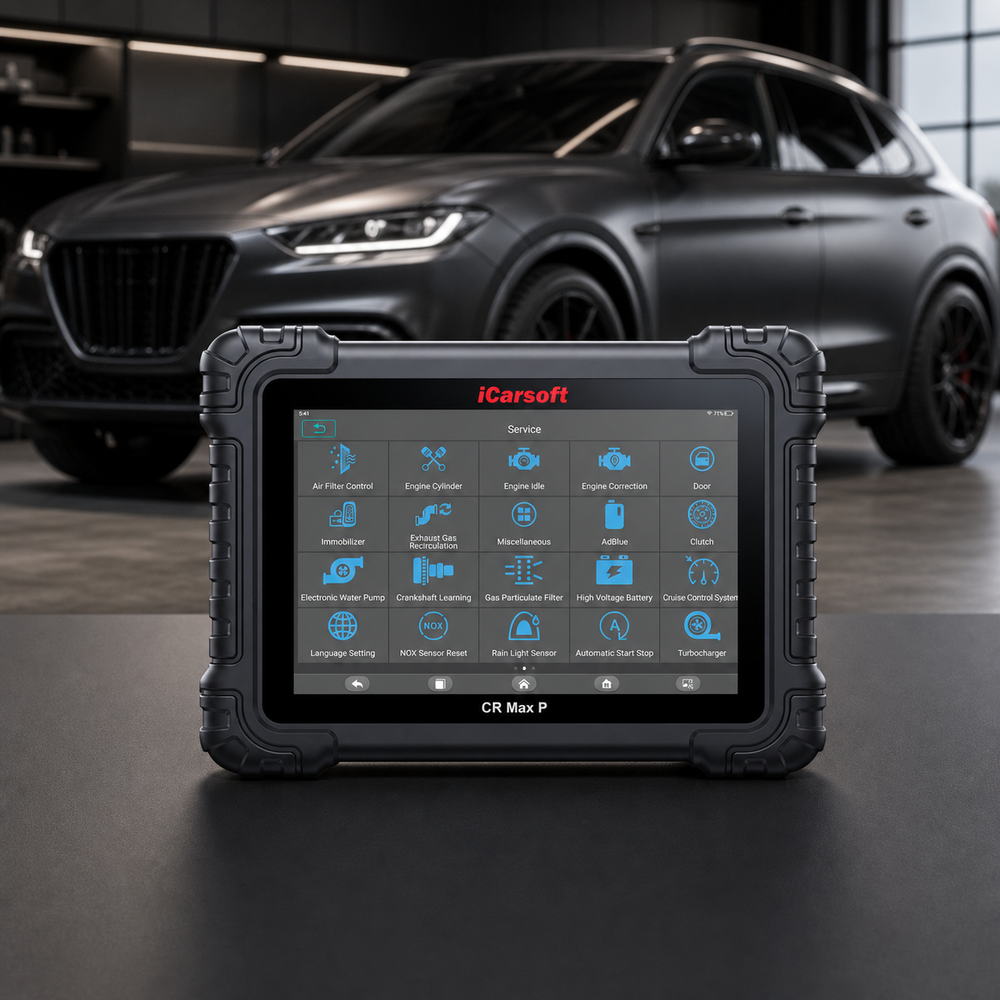
Preserve the restraints-controller messages and SRS safety boundaries evidence
iCarsoft CR Max P
Review supported codes and relevant live data together. Confirm the exact VIN, controller access, PIDs and any requested active test with iCarsoft before purchase; generic product capabilities do not guarantee a U0151-specific function.
Check current CR Max P price and availabilityCheck CR Max P compatibility by VINThe official product page describes supported full-system diagnostics, available live data, freeze frame and diagnostic reports; exact controller coverage and active tests depend on the VIN and software. Confirm the requested function by VIN before purchase. Follow OEM prerequisites and stop for abnormal operation.
Know the measurement boundary. Scan data describes ECU-provided information; it does not directly prove the physical condition of the restraints-controller messages and SRS safety boundaries. Where required, use approved system scan access, the VIN wiring diagram and the specified electrical test equipment and compare reported values with the relevant measured evidence.
Verify the U0151 Repair
After repair, verify installation, clearance and required setup. Save the final findings and clear only erasable records as instructed. Battery disconnection is not a repair.
Run the manufacturer's applicable verification conditions in a safe workshop or route. Compare the original operating state with current data for the restraints-controller messages and SRS safety boundaries, and check current and pending faults in related modules. A clean start or idle period does not prove the repair; use the OEM functional check for the affected system.
Compare the original and final fault status. Record the functional-check result and whether the original event returned.
If U0151 returns, compare its suffix, status, failure order and operating conditions with the saved baseline before replacing another part. Revisit the failed branch and inspect anything disturbed. Confirm the prescribed affected-system functional verification separately from code clearing.
Verification follows the system involved. After saving the original evidence, use the OEM procedure to clear erasable records, complete any required calibration or functional check, and compare the final module status with the original warning and fault conditions.
Related Restraints-Controller Messages And SRS Safety Boundaries Code Guides
Compare the related monitor families below. Shared symptoms or components do not make their repair procedures interchangeable.
U0151 Frequently Asked Questions
Can I test airbag wires with a multimeter to diagnose U0151?
Do not use ordinary probing or power tests on deployment circuits. A communication fault requires the approved SRS procedure, permitted test points and qualified equipment for that vehicle.
What should I check first for U0151?
Save every module's codes and freeze frame before clearing. Confirm the full definition, suffix and VIN architecture. Then inspect recent collision repair, interior wiring, battery or restraint-system service, connectors and shared supplies. Those facts determine whether the next test needs approved system scan access, the VIN wiring diagram and the specified electrical test equipment or a manufacturer-specific functional procedure.
Can I drive with the U0151 code?
An active SRS warning requires qualified diagnosis. Do not probe, energize or substitute resistors in deployment circuits, bypass restraint warnings or promise airbag operation from a scan result. Arrange towing when the vehicle is unsafe to operate. The DTC alone cannot establish a safe driving distance.
Why did U0151 return after a part was replaced?
A returned U0151 needs its suffix, reporting module and operating state compared with the baseline. Complete the prescribed SRS self-check, warning-lamp and configuration verification. Document unresolved restraint faults even if U0151 becomes historical or the module responds again.
What should a U0151 repair estimate include?
Ask for the failed-test evidence and a VIN-specific breakdown of diagnosis, parts, labor, taxes, required setup and verification. A code alone cannot establish the repair price.
Can CR Max P diagnose and clear U0151?
On a supported vehicle, CR Max P can organize available faults, freeze frame, live data and reports, and can clear erasable records after repair. Confirm exact ECU coverage. It cannot replace the OEM functional procedure or physical measurements for the restraints-controller messages and SRS safety boundaries.
The iCarsoft Official Store Technical Team maintains the store's fault-code library. This guide organizes published technical references and verified product information; it does not document a hands-on test of a particular vehicle or claim an individual engineer's review.
Technical and cost references
- Autel AL519 DTC definitions — communication-code terminology. Definition table only; no universal test limits or failed-part conclusion.
- Subaru Module 602 — missing airbag-module CAN data. Bounded OEM application example; scope and exceptions explained in the meaning section.
Product information: Official iCarsoft CR Max P page.
Editorial note: General diagnostic education, not a substitute for the owner's manual, current VIN-specific service information or professional inspection. Test limits, procedures, coverage and costs vary. Related articles provide context; apply only the specifications and repair procedures that match the vehicle. No universal failure rate, repair price or outcome is implied.


