

Quick answer
P2562 means Turbocharger Boost Control Position Sensor “A” Circuit. The engine controller detected an electrical or signal-integrity fault in the OEM-defined position-feedback path used by a wastegate, variable-geometry turbo or other boost-control actuator. It does not identify a universal pin, voltage or failed part, and it does not prove that the complete turbocharger needs replacement. Save the scan evidence, identify the exact actuator architecture, test the circuit, then verify linkage, travel and any required basic setting.
A turbocharger can control exhaust flow with a pressure- or vacuum-operated wastegate, an electronic wastegate motor, or a variable-geometry vane actuator. The position sensor may be external, built into the actuator, or communicated through actuator electronics. That variation is why P2562 must be diagnosed from the VIN, engine code and wiring diagram rather than a generic component location.
1What Does the P2562 Code Mean?
The standardized definition is “Turbocharger Boost Control Position Sensor ‘A’ Circuit.” The word circuit is intentionally broad. It does not say low, high, intermittent or range/performance.
P2562 tells you that the reporting controller found a problem with the position-feedback circuit it labels A. Depending on the application, the monitor may supervise a reference supply, sensor ground, analog signal, PWM or encoded signal, actuator electronics, internal communication or a combination of those paths.
The neighboring descriptors select different branches: P2563 is range/performance, P2564 is circuit low, P2565 is circuit high and P2566 is intermittent. Do not rewrite P2562 as one of those faults or apply a universal 0.5-to-4.5-volt rule. Even when a manufacturer publishes a voltage threshold, it applies only to the stated engine and calibration.
2How the Boost-Control Position Circuit Works
The ECM calculates desired boost, commands an actuator, and uses position feedback to verify the movement of a wastegate or variable-geometry mechanism. P2562 focuses on the integrity of that feedback path; boost pressure performance and desired-versus-actual travel may be evaluated by separate codes.
Heat and movement warning: turbocharger housings, exhaust components and actuator linkages can burn or crush. Let the engine cool, keep hands and tools clear during active tests, and never loosen or adjust a rod without the exact OEM procedure.
3Common P2562 Symptoms
The MIL, glow-plug or powertrain warning may appear even when the position circuit is stable at the moment of inspection.
The controller may disable or limit boost, producing slow acceleration, turbo lag or a limp-home strategy.
Acceleration may surge or feel flat when the actuator cannot be controlled or its reported position is not trusted.
Underboost, overboost, boost-control, sensor-supply or communication codes can add smoke, hesitation or abnormal response.
Symptoms vary by engine and failure strategy. A pure circuit fault may appear before obvious boost loss. New whistling, scraping, siren-like noise, heavy smoke or oil consumption points beyond the electrical code and requires immediate mechanical inspection.
4What Can Cause P2562?
Do not rank parts without application data. Official bulletins show that similar P2562 complaints can lead to a connector repair, position-sensor adjustment, separately replaceable actuator, linkage correction, software check or turbo assembly depending on the exact vehicle.
- Connector or terminal problem: loose lock, backed-out pin, corrosion, fretting, water, oil or poor terminal tension at a heat- and vibration-exposed actuator.
- Harness damage: melted insulation, chafing, broken strands, excessive resistance, short to ground or voltage, or a poor repair near the exhaust and turbocharger.
- Supply or ground fault: missing OEM-defined reference, unstable shared supply, poor sensor ground, actuator-module power or ECM ground problem.
- Position sensor failure: the sensing element may be separate or integrated into an electronic wastegate, VGT or charge-pressure actuator.
- Binding or misadjustment: corrosion at a rod pivot, bent linkage, seized wastegate, restricted vanes or an incorrect rod setting can prevent expected position and stress the feedback path.
- Vacuum-control problem: on applicable systems, a kinked hose, leak, failed diaphragm or control valve can prevent travel even though the position sensor circuit itself is intact.
- Basic setting or calibration issue: an actuator may require a specified adjustment, learn or software action after service. Apply only the exact-VIN procedure.
- ECM or complete turbo fault: consider either only after circuit, actuator serviceability and mechanical checks support that repair level.
5Is P2562 Safe to Drive With?
Stop driving and arrange service for severe power loss, unstable boost, heavy smoke, oil leakage, a flashing warning, overheating, abnormal turbo contact noise or an engine that will not accelerate safely with traffic. Do not tow a trailer or demand boost from a vehicle in reduced-power mode.
A steady warning with normal performance may permit a short, gentle trip if the owner's manual allows it, but there is no universal safe mileage. A feedback-circuit fault can make boost control unavailable without warning. Avoid hard acceleration, steep grades and highway merging until the cause is known.
Do not reach into an intake, spin a compressor wheel with the engine running, touch hot exhaust parts, or perform an actuator sweep with hands near the linkage. Turbo oil leaks and loose charge-air connections also require fire and runaway precautions appropriate to the engine.
6How to Diagnose P2562 Step by Step
-
Save the complete scan before clearing anything
Record the reporting module, full P2562 description and suffix, current/pending/history status, freeze frame, battery voltage, RPM, load and all companion boost, actuator, supply, network, MAP, MAF, exhaust-pressure and DPF codes.
-
Identify the exact actuator architecture
Use the VIN and engine code to obtain the OEM wiring diagram, connector view, serviceability information and test plan. Confirm whether the vehicle uses an electronic wastegate, vacuum actuator with feedback, VGT actuator or integrated control module.
-
Inspect safely with the engine cold
Check connector locks, terminal fit, water or oil entry, heat damage, chafed wiring, missing clips and prior turbo repairs. Do not alter a rod, stop screw or lever position during the inspection.
-
Verify battery, module power and grounds
Test the 12-volt system and the ECM or actuator-module feeds and grounds under load. Resolve shared-reference or supply codes first, because one unstable circuit can disturb several sensors.
-
Compare the supported live data
Review desired and actual actuator position, position-sensor value, duty or motor command, desired and actual boost, MAP, barometric pressure and relevant temperatures. PID names and normal direction can vary, so use OEM definitions rather than assuming that 0% means open or closed.
-
Test the position circuit as designed
Back-probe only where the manual permits. Measure the specified supply, loaded ground and signal with a DVOM or scope. For PWM, encoded or module data, average meter voltage may be misleading; never short a reference or apply battery power to a signal pin.
-
Use a controlled wiggle or actuator test
Watch the graph while gently moving accessible harness sections. If the vehicle and tool support an actuator test, run it only with the engine state, temperature and safety clearance required by the OEM procedure. Keep everyone away from moving linkage.
-
Separate electrical integrity from travel
If supply, ground and signal fail, stay on the circuit branch. If the signal is electrically valid but travel is short, slow or stuck, inspect vacuum, diaphragm, rod, lever, wastegate, vanes and mechanical adjustment using the manufacturer procedure.
-
Check bulletins, adjustment and basic setting
Some applications require a cold key-on voltage check, rod adjustment, actuator replacement or basic setting; others service only a matched turbo assembly. Confirm exact model, year, engine, part number and prerequisites before applying a bulletin.
-
Repair the proven fault and reproduce the monitor
Complete required coding, adaptation or initialization, clear codes only after saving evidence, graph the feedback through the permitted range, road-test under safe load and rescan for current and pending faults.
7P2562 Repair Paths
The repair must match the proved failure and the vehicle's parts catalog. These paths are alternatives, not a sequence of parts to install.
Repair terminals, connector seals, heat-damaged wiring, reference supply, loaded ground or actuator-module power with approved parts and routing.
Replace a leaking hose, diaphragm or control valve, or correct binding and adjustment only when the exact service procedure identifies that path.
Some designs offer the position sensor, vacuum unit or electronic actuator separately and require precise installation plus a basic setting.
Other designs integrate the sensor, motor or VGT electronics into a matched unit. Replace the assembly only after the external circuit and application-specific tests pass.
Software, adaptation or rod adjustment is valid only when the OEM information for the exact VIN directs it. Never move a factory stop screw or copy another engine's rod length, sensor voltage or learned position.
8Using iCarsoft CR Eagle P for P2562
On supported vehicles, CR Eagle P can scan the engine and related modules, preserve P2562 status and freeze frame, and graph the boost request, actual boost, turbo actuator command or position data the ECU exposes. Supported active tests and Turbocharger Learn or basic-setting functions vary by VIN, engine, ECU and software.
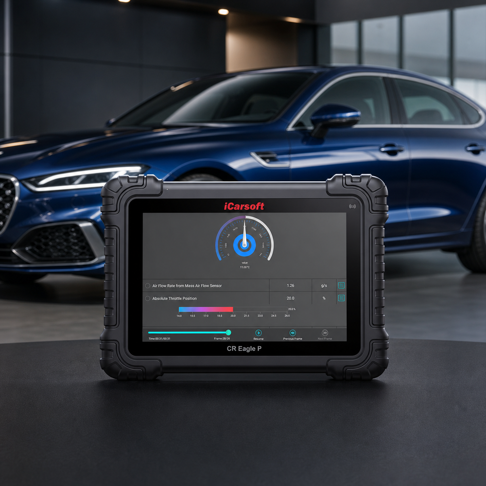
Recommended diagnostic platform for P2562
iCarsoft CR Eagle P
Use full-system scanning, freeze frame and supported live-data graphing to compare the available actuator command, feedback and boost data. Confirm exact coverage before relying on an active test or turbocharger learn.
Check current price & availability · lifetime Wi-Fi updates
View CR Eagle P Check compatibility by VINTool boundary: CR Eagle P does not physically measure reference voltage, voltage drop, resistance, duty cycle, frequency, vacuum or linkage travel. Use the OEM wiring diagram, DVOM, oscilloscope, vacuum/pressure equipment and mechanical inspection where required. Never assume every vehicle supports a turbo sweep or learn.
9How Much Does P2562 Cost to Fix?
These 2026 US parts-and-labor figures are planning ranges, not quotes. Each row is a different confirmed repair outcome, so do not add them together. VIN, turbo design, access, sensor serviceability, labor rate, calibration, gaskets, oil/coolant, taxes and related damage can materially change the total.
| Confirmed repair path | Typical US planning range |
|---|---|
| Professional diagnosis and signal testing | $120–$250 |
| Connector, pigtail or local harness repair | $150–$700 |
| Separately serviceable position or feedback sensor | $225–$500 |
| Boost-control solenoid or vacuum-control valve | $200–$450 |
| Electronic wastegate or VGT actuator and setup | $500–$1,500 |
| Integrated actuator or turbocharger assembly | $1,500–$5,500 |
Ask what circuit measurement, scan trace or mechanical test supports the estimate. A generic P2562 scan cannot establish that a complete turbocharger is defective, and a boost-pressure sensor estimate may not match the boost-control position sensor described by this code.
10How to Confirm the Repair
- Verify connector locks, approved heat protection, harness clearance and stable loaded power and ground.
- Complete the required actuator adjustment, basic setting, calibration, coding or learn for the exact engine.
- Graph position command and feedback through the permitted operating range and repeat a safe heat or vibration check.
- Confirm desired and actual boost response only after the position circuit is stable and companion faults are repaired.
- Road-test with a second person or data recording; never watch the scanner while driving.
- Run the OEM monitor, rescan every module, and confirm no current or pending P2562-family code returns.
A cleared light is not enough: the position feedback must remain electrically valid, the actuator must complete its required setup, and boost control must behave normally under the specified verification conditions.
11Related Turbocharger Codes
Related codes identify different electrical or performance branches. Use each only when it is actually present in the full-system report.
12P2562 FAQ
What does code P2562 mean?
P2562 means Turbocharger Boost Control Position Sensor "A" Circuit. The engine controller detected a fault in the OEM-defined position-feedback circuit used to monitor a wastegate, VGT or other turbo boost-control mechanism.
What is the difference between P2562 and P2563?
P2562 is the base position-sensor circuit descriptor. P2563 is the related range/performance descriptor, often used when feedback is present but implausible or does not meet the application-specific position test.
Does P2562 mean the turbocharger is bad?
No. A connector, harness, reference supply, ground, sensor, actuator, vacuum component, linkage, basic setting or application-specific software issue can set the code. Some designs service the actuator separately from the turbocharger.
Can I drive with P2562?
There is no universal safe distance. Avoid boost, towing and highway merging, and stop for severe power loss, smoke, oil leakage, abnormal turbo noise or an urgent warning. Follow the owner's manual and tow when needed.
Where is turbo position sensor A located?
The code does not define a universal location. The sensor may be built into an electronic wastegate or VGT actuator, attached to a vacuum unit or integrated into a turbo assembly. Use the VIN and engine code to identify it.
Can CR Eagle P fix P2562 by itself?
No scan tool can repair wiring, vacuum parts or turbo hardware. On supported vehicles CR Eagle P can save codes and freeze frame, graph available command and position data, and run supported tests or setup functions, but physical testing is still required.
How do I know P2562 is permanently fixed?
Complete the OEM repair and required basic setting, verify stable circuit feedback through the permitted actuator range, confirm normal boost response, reproduce the original conditions and rescan for current and pending faults.
Technical and cost references
- Definition: BMW official SAE P-code list and SAE J2012 diagnostic trouble code standard.
- Vacuum and application-specific examples: Volkswagen Bulletin 21-15-06, covering specified engines and multiple turbo-control fault paths.
- Electronic wastegate service example: Hyundai EWGA diagnosis and replacement guideline, including inspection before parts selection.
- Architecture and threshold boundaries: Ford 2023 diesel OBD summary and GM smart VGT system description.
- Product and US cost anchors: official CR Eagle P product page; RepairPal estimates for electrical diagnosis, turbo boost sensor replacement, boost-control solenoid replacement and turbocharger assembly replacement.
Editorial note: This guide provides general diagnostic education, not a substitute for the service manual, safety instructions or a hands-on inspection of the exact vehicle. Component location, signal type, specifications, serviceability and scan-tool coverage vary. Prices are illustrative US planning ranges and are not quotations.


